By William J. Esposito
R0.3, 5/12/14
Introduction
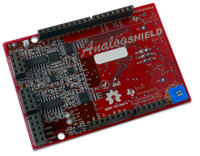
The analog shield offers a high fidelity and easy way to connect your Arduino to analog circuits. In order to do this, the Analog Shield* provides:
•
4 Channel,
16 bit 100ks/s SAR ADC ADS8343.
•
4 Channel 16
bit 100ks/s DAC DAC8564.
•
Variable
+/-7.5V Supply TPS61093.
•
Fixed +/-5V
Supply.
•
A small area
for a breadboard.
•
Software
read and write to the ADC/DAC with a single line of C.
Download the software at
https://github.com/wespo/analogShield.
The Analog Shield hardware is available from Digilent at http://www.digilentinc.com/analogshield
In
addition to providing many of the features available on other prototyping or
breadboard shields, this shield provides substantially higher resolution inputs
and outputs than an Arduino Uno does natively, as well as providing the bipolar
inputs and supplies needed to drive many useful analog circuits.
The Analog shield communicates with the Arduino using the SPI protocol. The Analog-to-Digital input conversion (ADC) and Digital-to-Analog output conversion (DAC) both use the standard Arduino SPI bus pins and independent chip selects
Applications
The Analog Shield allows access to many signals that cannot reliably be recorded or generated using the standard pins on the Arduino.
A few demos using the analog shield have been developed.
· Sine wave / function
generator (using direct digital synthesis)
·
FFT spectrum
analyzer
·
Polyphonic music
generator
·
4 channel
low bandwidth oscilloscope
·
Lissajou
diagram generator
·
XY-analog scope
display driver
These demos are each explained in their own associated documentation, found on this website
Hardware
Expansion Header
The left hand edge of the Analog Shield contains a three pin dual row female headers. The first columns on the connectors contain inputs and outputs of all of the analog shield’s peripherals. All of the connections on the second column are referenced to a shared ground.
Analog Inputs
The Analog Shield provides 4 channels, of 16 bit of Analog-to-Digital input conversion (ADC). As described below, to sample one of the analog input requires only a single line function call:
analog.read(channel);
Analog read takes a channel as an input and returns a 16 bit unsigned integer.
These inputs are buffered with an op-amp to protect the circuitry of the ADC, and a simplified circuit diagram of the inputs has been printed directly on the board.
Analog Outputs
As well as inputs, the Analog Shield has 4 channels of Digital-to-Analog output conversion (DAC) for analog output. The outputs of the Analog Shield function slightly differently from the Analog outputs of the Arduino itself. The standard Arduino analogWrite(pin, value) function initiates a Pulse Width Modulated square wave that only approximates the desired output value over time. While this behavior is suitable for many applications, there are some analog circuits where it is important to have an actual stable output value. The DAC on the Analog Shield serves this purpose nicely. Values written to these ports remain stable until a new value is written to the selected port. As described below, in order to write to one of the analog output channels on the expansion connector (labeled OUT0-OUT4), one simply has to call:
analog.write(pin, value);
The analog.write() function takes an unsigned 16-bit unsigned integer as an input.
As with the inputs, the outputs are buffered with an op-amp to protect the circuitry of the DAC, and a simplified circuit diagram of the inputs has been printed directly on the board.
Power Supply
In addition to the inputs and outputs, the Analog Shield also includes an integrated power supply. Unlike the Arduino’s included power supply, the supply on the Analog shield is bipolar – meaning that it provides both positive and negative voltages.
The onboard power supply includes five outputs, +5V, -5V, +Vadj, and –Vadj, and 2.5V Vref.
In addition, to the fixed +/-5V supply pins, The Analog Shield also includes adjustable +/-7.5V pins. The voltage of these pins is controlled using the potentiometer located in the lower right corner of the Analog Shield. Adjusting the potentiometer will adjust the voltage of the +Vadj supply and the –Vadj supply simultaneously, keeping the two supplies balanced at the same voltage (but with the opposite polarity). For example, one might adjust the potentiometer to produce +3.3V on the +Vadj pin, which would produce an output of -3.3V on the –Vadj pin and thus a potential between the two pins of 6.6V. Turning the potentiometer clockwise will increase the voltage differential, while turning it counterclockwise will decrease it.
Finally, a +2.5V reference output is provided to offer a ‘center’ point between 0 and 5 volts, in case a single rail (+5V to 0V supply) circuit needs a center voltage reference point.
Prototype Area
The center of the board is intentionally left open. It includes a silkscreened drawing that provides a high level schematic of one channel of the ADC and one of the DAC, as mentioned above. This area has been left free of any top mounted components, and a miniature breadboard has been included with the shield, to be affixed in this area, for use in constructing circuits.
Software
Included with the Analog Shield is a simple driver library. It attempts to provide a similar interface to the existing Analog read and write functionality. To install the driver library see the document “Analog Shield – 02 First Time Setup”. To include the library in a sketch, once it is installed, it is simply added to a sketch with:
#include <analogShield.h>
Once the shield library is included, the sketch will have access to a variable called analog, which has access to all the methods associated with the shield. The following are the six most important methods associated with the shield.
unsigned int read(int channel, bool mode = false);
This method samples the selected analog input. ‘mode’ is an optional parameter. False (the default value) is normal single ended mode where each analog pin is referenced to ground. True enables ‘differential’ mode, where the value returned is the difference between the voltages on pairs of adjacent inputs (i.e. IN0-IN1 and IN2-IN3). Read returns an unsigned integer.
signedRead(int channel, bool mode = false);
Signed read behaves identically to read, but returns a signed integer.
write(int channel, unsignedint value);
write(unsigned int value0, unsignedint value1, true);
write(unsignedint value0, unsignedint value1, unsignedint value2, true);
write(unsignedint value0, unsignedint value1, unsignedint value2, unsigned int value3, true);
These methods allow writing to the Analog Shield’s analog output. The first method writes to any arbitrary selected channel. The next three methods write to two or more channels simultaneously (but only write to specific channels, i.e. 0 and 1 instead of to any arbitrary pair of channels). The simultaneous update methods are useful for higher speed applications where a small delay between channel outputs will produce unwanted signals or timing issues. For example, to use the shield to drive the X-Y input of an oscilloscope to draw a circle, a delay between writing the X and the Y channels produces a ghost ‘ellipse’ drawn during the interim between the X and Y DAC updates.
The power supply is entirely analog and as such needs no software to operate, but the ADC (part number DAC8564) and DAC (part number ADS8343) are both SPI devices. Their datasheets are freely available from the manufacturers website and can be used to write your own software as need be, but this simple library should do the trick for most users.
Summary
Unlike the native Analog input of the Arduino, the Analog shield provides a 16 bit ADC, (as opposed to 10 bits provided by the Arduino UNO) offering greater precision (about 25dB) than the Arduino does natively. Additionally, the ADC works as a bipolar input, meaning that sense signals in the range of +/-5V can be measured without any additional hardware.
The onboard DAC provides a similar improvement in precision. The Analog Shield provides 16 bits of precision, and offers as much as 25dB better signal to noise ratio when driving a sinusoidal output at low frequency.
The analog shield provides a compact integrated power supply with fixed and adjustable outputs to allow a variety of analog circuits to be assembled with a minimum of wasted space and complexity.
Special thanks to Gregory Kovacs, Fernando Mujica, and Clint Cole and their respective teams at Stanford, TI, and Digilent for supporting this project to completion, as well as Domingo Garcia for his amazing work on board layout and to Laurent Giovangrandi for his support in program oversight and debugging.