By William J. Esposito, Doctoral Candidate and Gregory T.A. Kovacs, Professor of Electrical Engineering, Stanford University
R0.2, 5/13/14
Overview
Using concepts from trigonometry, a circle can be created from a sine
and a cosine function. More complex
shapes can be made by varying phases and frequencies.
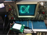
Figure 1: Prototype Analog Shield with Lissajous pattern generator with an oscilloscope.
With the Analog Shield DAC, two waves are output to the x- and y- axis inputs of an oscilloscope. One is set at a fixed frequency and the second varies over time.
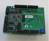
Figure 2: Prototype Analog Shield, with breadboard not attached.
The ratio of the frequencies on the x- and y- axes determines shape of the waveform displayed on the screen. If the frequencies are equal, a single loop is displayed. At a ratio of 2:1, a figure eight shape with two lobes appears. At 3:1, three lobes appear, and so on.
Hardware
The
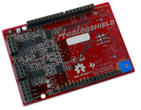
Lissajous Pattern Generator is built around the Arduino and the Analog Shield*
The
Arduino UNO R3 Can be found at:
http://store.arduino.cc/
The
Analog Shield can be found at:
http://www.digilentinc.com/analogshield
The demo also requires a two-channel oscilloscope with x-y mode for output.
Building the
Demo
In
order to build Lissajous demo, two
nonstandard Arduino libraries are necessary. For a guide on Arduino libraries
and how to install them, go to
http://arduino.cc/en/Guide/Libraries
The libraries required for the demo are:
The
TimerOne library (for the DDS sample clock)
https://code.google.com/p/arduino-timerone/
The
Analog Shield library (for analog input)
http://www.github.com/wespo/analogshield
The code itself for the Lissajous demo can be found at https://github.com/wespo under ‘Lissajous’, as well as in this document.
Once these libraries are downloaded and unzipped in four Arduino/libraries folder, be sure to re-open the Arduino IDE as it will not recognize libraries added while it is open. Once that is done, attach the Analog Shield to the Arduino Uno. Next, open the “Lissajous_curve” sketch with the Arduino IDE and upload it to the Arduino Uno.
Connecting the Output
Next, connect the channel one input of an oscilloscope between D0 and Ground on the Analog Shield. Connect the channel two input of the oscilloscope between D1 and Ground. Switch the oscilloscope to X-Y input mode and the image on the scope should appear to shift and swirl in patterns similar to figure 1. Switching the oscilloscope to standard time mode will show two sine waves (one on each respective channel), one at a fixed frequency and one varying in frequency over time.
How the Code Works
The Lissajous curve generator is based on DDS code outlined at in the DDS tutorial at http://www.digilentinc.com/analogshield. It uses a recorded single period of a sine wave stored in a table to generate an output waveform. It can adjust the output frequency via software, by controlling the rate at which the program steps through the table. By outputting two sine waves simultaneously (one of them phase shifted by 90° to generate a cosine), a Lissajous curve is produced.
The code for the Lissajous curve generator is attached here, and can be found at
http://www.digilentinc.com/analogshield
/* Lissajous Curve */
//12 bit long sine table
PROGMEM prog_uint16_t isinTable16[] = { <sine table omitted for space> };
#include <analogShield.h>
#include <avr/pgmspace.h>
#include <TimerOne.h>
unsigned long frequencyIncrement = 40000; //32 bits
unsigned long frequencyIncrement2 = 40000; //32 bits
unsigned long phaseAccumulator = 0; //32 bits
unsigned long phaseAccumulator2 = 0; //32 bits
void setup(){
Timer1.initialize(30); //100000
Timer1.attachInterrupt(circle);
}
void loop(){ //Sweeps frequency
frequencyIncrement2 =20000;
while(frequencyIncrement2 < 40000)
{
frequencyIncrement2 += 50;
delay(50);
}
delay(10000);
}
void circle() //this is it.
{
//increment the phase accumulator
phaseAccumulator += frequencyIncrement;
phaseAccumulator2 += frequencyIncrement2;
//peel off top bits ch 1
unsigned long tempPhase = (phaseAccumulator >>12);
unsigned int tablePosition = tempPhase & 0x0FFF;
tablePosition = tablePosition & 0x0FFF;
//peel off top bits ch 2
unsigned long tempPhase2 = (phaseAccumulator2 >>12);
unsigned int tablePosition2 = tempPhase2 & 0x0FFF;
tablePosition2 = (tablePosition2 + 1024) & 0x0FFF;
//look up and output sine wave values
unsigned int value =0;
unsigned int value2 =0;
value = pgm_read_word(isinTable16 + tablePosition);
value2 = pgm_read_word(isinTable16 + tablePosition2);
analog.write(value,value2, true);
}
Potential Improvements
The Lissajous curve generator could be used as a music visualizer by controlling the frequency variable with input from and Analog Shield ADC configured as a beat detector. It could also be used as a back end for a game where the user controls one of the frequencies with a potentiometer and the other is controlled via software, challenging the user to follow the frequency changes made by the software and maintain a circular output.
Disclaimer: This code and circuit was developed by William Esposito, Ph.D. Candidate in Electrical Engineering, Stanford University, in the Kovacs/Giovangrandi Laboratory in collaboration with Texas Instruments, Incorporated. All code herein is free and open source, but is provided as-is with no warranties implied or provided. Use of this code and the associated documentation is at the user’s own risk.