By William J. Esposito, Doctoral Candidate and Gregory T.A. Kovacs, Professor of Electrical Engineering, Stanford University
R0.6, 5/14/14
Overview
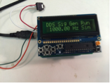
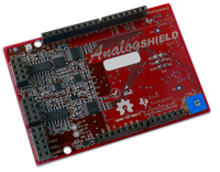
Figure 1: DDS Function Generator.
The Analog Shield Direct Digital Synthesis (DDS) Function Generator is a compact, low-frequency function generator capable of producing sine, square, triangle or sawtooth waveforms (figure 1).
DDS works by means of “playing back” a prerecorded waveform stored in a lookup table at a precisely controlled rate. One full period of the waveform is stored in an array on the Arduino. To create a wave output, the Arduino sends a single sample of the stored waveform out via the analog shield. It moves through the table outputting samples until it reaches the last sample in the array. Once it reaches the end, the program returns to the beginning of the table and repeats. In order to put out a waveform at a higher frequency, the program skips steps in the table. For example, if a step of 1 produces a 1Hz output, then outputting every 10th sample (a step of 10) would produce a 10Hz output. By calculating how many samples it has to skip, it can precisely generate any frequency it needs, up to half the rate at which it puts out samples (the Nyquist rate, where there are a minimum of two samples per waveform period, which assumes a sine wave… more samples per period are necessary for more complex waveforms).
Hardware
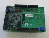
Figure 2: Protoype Analog Shield. The final shield is red.
The Analog Shield DDS is built around the Arduino and uses the TI/Stanford Analog Shield* (available from Digilent, figure 2) for signal output. The Analog Shield DDS also uses the Adafruit RGB LCD Shield kit for its user interface.
The Arduino UNO R3 Can be found at:
http://store.arduino.cc/index.php?main_page=product_info&products_id=195
The Adafruit RGB LCD Kit can be found at:
https://www.adafruit.com/products/714
The Analog Shield can be found at:
http://www.digilentinc.com/analogshield
In order to get a meaningful signal at more than a kilohertz, the DDS also needs a “reconstruction” filter on its output. The reconstruction filter is discussed in its own section, below, but the quality of the reconstruction filter will make a big difference in the quality of the signal produced
Building The Demo
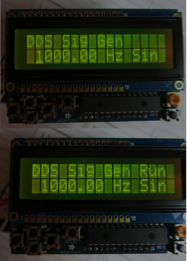
Figure 3: LCD with
cursor and
DDS running
In
order to build the Analog Shield DDS, four nonstandard Arduino libraries are
necessary.
For a guide on Arduino libraries and how to install them, go to http://arduino.cc/en/Guide/Libraries
The libraries required for the DDS are:
The Adafruit RGB-LCD Shield and MCP23017 libraries (For the LCD ) https://github.com/adafruit/Adafruit-RGB-LCD-Shield-Library
The TimerOne library (for the DDS sample clock)
https://code.google.com/p/arduino-timerone/
The Analog Shield library (for analog input)
http://www.github.com/wespo/analogshield
In case these libraries move in the future, the Adafruit LCD libraries are linked from the Adafruit Touch LCD Shield tutorial at
https://learn.adafruit.com/rgb-lcd-shield/
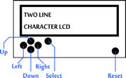
Figure 4: DDS Controls
The code for the DDS is available with this document at
http://www.digilentinc.com/analogshield.
A detailed discussion is included below, in the ‘How the Code Works’ section of this document.
Once these libraries are downloaded and unzipped in the Arduino/libraries folder, open the Arduino IDE and the “DDS_Generator” sketch. It is important to note that if the Arduino IDE was already open before the libraries were added, the IDE will need to be restarted to recognize the libraries.
Stack the LCD and Analog Shield on your Arduino. Next, click the “Upload” arrow in the top left to upload the DDS Function Generator to the Arduino.
Once the upload is complete, you will see a menu will appear on the LCD.
Controlling the Demo
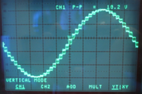
Figure 5: 1kHz sine wave with no reconstruction filter.
At startup, the Arduino waits for the user to set the frequency and wave output type.
To change the frequency, press up and down. The left and right buttons move the cursor and selects which digit the up and down buttons effect (figure 4). Moving the cursor past the lowest digit allows selection of the wave shape (sine, square, sawtooth, triangle).
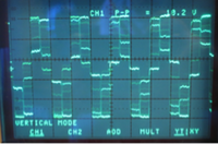
Figure 6: 10kHz sine wave with no reconstruction filter.
Once a timeout (5 seconds) occurs or the user presses ‘select’ the system will output the desired wave. When running, the word ‘run’ displays in the upper right corner of the LCD (figure 3).
To set a new waveform, press reset to return to the menu.
Output
Now that there is a signal coming out of D0 on the analog shield, the next step is to do something with the signal.
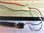
Figure 7: Headphone jack output. Orange wire (top) to D0, green wire (bottom) to the ground on the analog shield.
One option is to directly connect the output (D0) to an oscilloscope (as well as a ground from the shield to the ground on your oscilloscope probe, to complete the circuit).
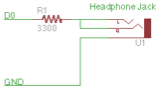
Figure 8: Headphone jack connector circuit
With a direct output, an oscilloscope will show a fairly clear waveform at low frequencies (up to 1kHz or so, figure 5), although it will have a somewhat stair-step nature. At higher frequencies, the waveform will break down. This is due to the nature of the DDS. At higher frequencies, the DDS skips more steps, and each step will therefore make a larger vertical jump. At a high enough frequency, the signal begins to look like a rolling square wave. To allow the DDS to work at higher frequencies a reconstruction filter is needed, which will be addressed below.
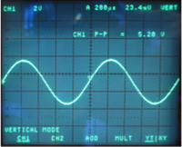
Figure 9: 1kHz sine through high quality filter.
If an oscilloscope isn’t handy, the output can be heard with headphones. One advantage of this is that most headphones naturally act as a low pass filter with a cutoff at or below 20kHz. To connect your headphones you’ll need a headphone jack and a resistor with a value of at least 3.3kΩ. The resistor is critical because it will limit the volume put out through the headphones, saving your ears and your headphones from damage. Figures 7 and 8 show this circuit.
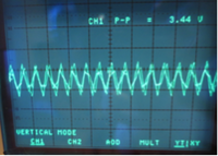
Figure 10: 10kHz signal through RC filter, with the same scale as figure 9.
Reconstruction
Filter
To
improve the DDS, a reconstruction filter can be added.
The purpose of the reconstruction filter is to remove the stair-step nature of our sampled sine wave. Figure 9 shows the relatively low frequency 1kHz output after passing through the high quality filter that will be discussed in a moment. Note the drastic improvement in this output when compared to the same wave seen without a filter in figure 5.
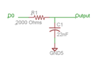
Figure 11: Simple RC filter.
The reconstruction filter should be a low pass filter which removes the sharp (40kHz high frequency) steps in the output without weakening the lower frequency (1Hz - 16kHz) signal that is the actual intended output.
The simplest filter that can be implemented is a passive RC (resistor-capacitor) low pass filter. Such a filter will improve the signal, but its simplicity means that it will only weakly attenuate higher frequencies. This means that the resulting signal is less of an improvement when compared to a better filter.
To make a simple RC Filter, connect a resistor of 2kΩ between D0 on the analog shield and our output, and a capacitor of 22 nanofarads (nF) between our output and ground as shown in figure 11.
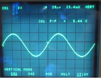
Figure 12: The same 10kHz sine wave through an 8th order reconstruction filter, with an 18kHz cutoff.
This
will create a filter with a ‘cutoff’
(half power) point at:
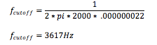
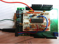
Figure 13: 8th order reconstruction filter with an 18klHz cutoff constructed on the prototyping area of the Analog Shield.
This will help our resulting signal by attenuating high frequency noise. It will not provide optimal performance, however, as the signal of interest is often above 10kHz and will be attenuated as well. Figure 10 shows the 10kHz signal as observed through this RC filter. Note that it is closer to a sine wave than figure 5 above, but is still a poor quality output.
To maximize the frequency that can be reproduced with the DDS, a complicated 8th order active low pass filter can be implemented. Such a filter uses operational amplifiers (op-amps) to allow numerous successive stages of high frequency removal without a loss in signal strength. Figure 12 shows the same signal as figure 10, passed through one of these high quality filters.
A full filter design has been attached to this document for an 8th order filter with an 18kHz cutoff that will allow for a clear DDS output up to a 16kHz sine wave. The design for this filter has been included as figure 17 at the end of this document.
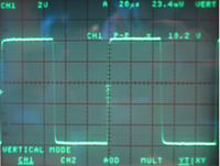
Figure 14: 10kHz square wave with no reconstruction filter
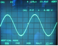
Figure 15: 10kHz square wave through 8th order reconstruction filter with an 18kHz cutoff.
There is a caveat, however. Sometimes, the desired output waveform needs to have sharp edges. In an extreme example, the DDS can output a square wave, which has the sharpest possible edge. By passing that signal through the reconstruction filter, the output waveform would be reduced to an approximation of the sine wave output at 10kHz (see figures 14 and 15). This is due to the nature of a square wave itself, whose sharp edges are the result of harmonics which are attenuated through the reconstruction filter.
How the Code Works
On the Analog Shield, the DDS has been implemented in a very standard configuration.
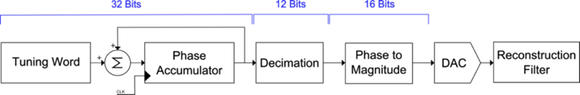
Figure 16: DDS Software block diagram
The DDS stores a phase offset, which represents a position in a hypothetical infinite waveform. Each sample cycle, the DDS routine increments that phase offset by its stride size (tuning word). Since only one period of the waveform is actually stored in memory, the DDS computes the offset with respect to a single wave cycle and uses that as a table lookup. The resulting value is then sent to the DAC for conversion to a voltage output. By storing the phase in a higher precision word than the table, the program avoids having to perform complicated carry offset operations every time it generates a sample (figure 16).
The actual DDS routine is moderately complex as it supports multiple waveforms and controls the LCD and menu system. A shortened version of the main code (attached below) shows how the block diagram can be simply implemented with careful coding.
/* Direct Digital Synthesis */
//12 bit long (4096 length) sine wave table
PROGMEM prog_uint16_t isinTable16[] = {<sine wave table omitted for space>};
#include <analogShield.h> //Analog Shield
#include <avr/pgmspace.h> //Sine Wave Storage
#include <TimerOne.h> //Timer Control
//DDS variables
volatile unsigned long tuningWord = 0;
volatile unsigned long phaseAccumulator = 0; //32 bits
bool toggle = false;
void setup(){}
void loop() {//takes user input and the goes into DDS forever.
Timer1.initialize(16); //Setup the timer for DDS
Timer1.attachInterrupt(dds); //start DDS
while (1) {}; //wait forever. Reset Arduino for new frequency.
}
}
//DDS code
void dds(){ //Direct Digital Synthesis Lives Here.
unsigned int value; //value to output on DAC
unsigned long tempPhase; //calculated phase for this sample
//Increment the phase accumulator by the value stored in the tuning word.
phaseAccumulator += tuningWord; //32 bits
//use only top 12 bits of 32 bit phase accumulator
tempPhase = (unsigned long)(phaseAccumulator >> 20);
//Get Sine Value
value = pgm_read_word(isinTable16 + tempPhase);
//write the result to the output.
analog.write(0, value);
}
Additional Caveats About the DDS
The waveform itself of a DDS is band limited by the sample clock used to drive the digital to analog converter. In the case of the Analog Shield DDS, the sample clock runs around 40,000 samples/second. This means that a sharper edge (as found in the square and sawtooth waveform) can’t be accurately reproduced. This phenomenon results in apparent jitter on the sharp edges of the waveform as they appear to move back and forth in time by one sample.

Figure 17: DDS reconstruction filter with 18kHz cutoff.
Notes
[1] Maxim
Semiconductor has produced a whitepaper, MT-085 which explains DDS much more
rigorously. It can be found at:
http://www.analog.com/static/imported-files/tutorials/MT-085.pdf
Disclaimer: This code and circuit was developed by William Esposito, Ph.D. Candidate in Electrical Engineering, Stanford University, in the Kovacs/Giovangrandi Laboratory in collaboration with Texas Instruments, Incorporated. All code herein is free and open source, but is provided as-is with no warranties implied or provided. Use of this code and the associated documentation is at the user’s own risk.