By William J. Esposito
R0.3, 5/10/14
Installing the Libraries
Download the software at https://github.com/wespo/analogShield.
To use the Digilent Analog Shield*, place the contents of the provided AnalogShield.zip in a subfolder called ‘libraries’ within the folder where Arduino sketches are stored. The final folder structure like figure 1, on Windows, Mac, and Linux machines:
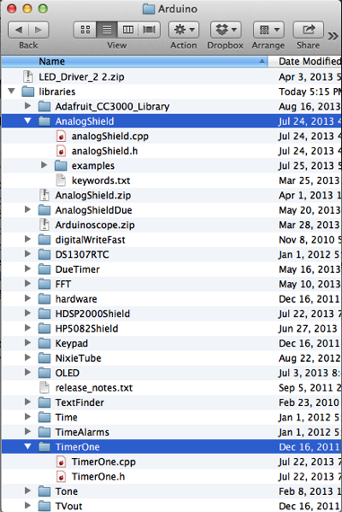
Figure 1: Libraries subfolder inside the Arduino sketch folder on Mac OSX.
Note that there are several other folders depicted here, each one an unrelated Arduino sketch. It is perfectly fine to have other folders within the “libraries” folder. If analogShield.cpp is not on the first folder level below AnalogShield, then the Arduino IDE will likely be unable to find the files and fail to compile your sketch. If there is not already a ‘libraries’ folder within your Arduino sketch folder, create a folder called ‘libraries’ and put the code in it. Arduino will find it once the IDE is restarted.
If the libraries are added within a sub-subfolder, Arduino will fail to find it, as in figure 2. The Arduino environment does not look below the first level of folders after ‘libraries.’
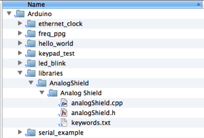
Figure 2: This folder structure will fail to compile.
Be sure to restart the Arduino IDE once the library is installed. New libraries are only detected when the IDE is first opened, so if the IDE was already open when the folders were copied over, it should be closed and restarted before proceeding.
First Sketch
To start using the Analog Shield in your sketches, a #include<analogShield.h> statement is required the top of the sketch, like any other library. Once the analogShield library is included, the read and write to the inputs and outputs of the shield can be read by calling the analog.read() and analog.write() methods, respectively.
An extremely simple sketch is included as an example with the Analog Shield library, called “passthrough” and can be found within the examples dropdown once the library has been installed. This pass through library takes a voltage measured on input pin A0 of the Analog Shield and replicates it on the output pin D0.
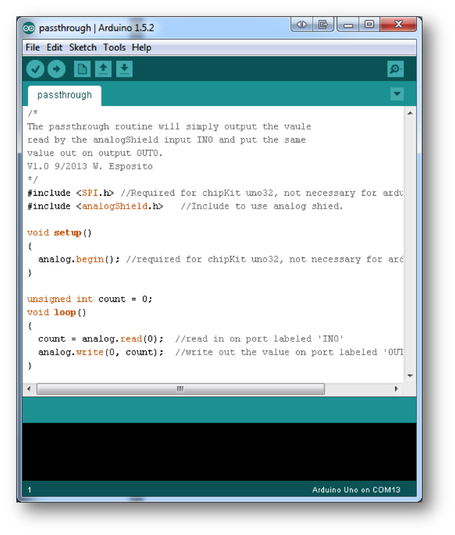
Figure 3: Simple passthrough example.
Try uploading this sketch to the Analog Shield and applying a test voltage from the Analog Shield’s onboard supply using a breadboard wire. Measure the output using a voltmeter connected between D0 and ground.
A number of other, more complex examples have been developed, and are discussed in more detail in a series of “instructable” style application notes.