By
William J. Esposito, Doctoral Candidate and Gregory T.A. Kovacs, Professor of
Electrical Engineering, Stanford University
R0.5,
5/13/14
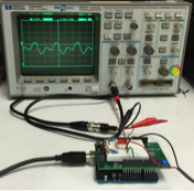
Figure 1: Polyphonic music Player with an oscilloscope.
Overview
The Analog Shield Polyphonic music Player plays a converted 4-voice music file through normal headphones or a stereo system.
Hardware
The Polyphonic Music Player is built around the Arduino and uses the Digilent Analog Shield* for signal output, combining the four channels with a simple resistive mixer.
The
Arduino UNO R3 Can be found at:
http://store.arduino.cc/
The
Analog Shield can be found at:
http://www.digilentinc.com/analogshield
Figure 2: Analog Shield, with breadboard not attached. Protoype Analog Shield. The final shield is red.
A full description of the resistive mixer is found below, but the parts requirements include (for monaural output):
- 4x 330Ω Resistors
- 1x 3.3kΩ Resistor
- 1x 0.047µF Capacitor
- 1x 3.5mm Headphone Jack
Building the Demo
In order to build Polyphonic music Player, two nonstandard Arduino libraries are necessary. For a guide on Arduino libraries and how to install them, go to
http://arduino.cc/en/Guide/Libraries
The libraries required for the visualizer
are:
The
TimerOne library (for the DDS sample clock)
https://code.google.com/p/arduino-timerone/
The Analog Shield library (for analog output)
http://www.github.com/wespo/analogshield
In
case these libraries move in the future, the Adafruit LCD libraries are linked
from the Adafruit Touch LCD Shield tutorial at
https://learn.adafruit.com/rgb-lcd-shield/
Once these libraries are downloaded and unzipped in four Arduino/libraries folder, be sure to re-open the Arduino IDE as it will not recognize libraries added while it is open. Once that is done, attach the Analog Shield to the Arduino Uno. Next, open the “Polyphonic_music” sketch with the Arduino IDE and upload it to the Arduino Uno. Once the demo is uploaded, one tone will be output from each of the four DAC outputs on the analog shield (D0-D3).
Included with the player is an example song, which plays when the sketch is uploaded.
At this point, tones can be heard directly at the outputs, by connecting a headphone (and a current limiting resistor of at least 330 Ohms). To produce a combined sound output, a simple filter will have to be constructed, which will be described next.
Connecting the Output
The most straightforward way to output all four voices at one time is to use resistors to build a simple four input low-pass mixer / filter at the output of the Analog Shield’s DAC. It is crucial that all four independent resistors be used before the junction instead of one after, as the presence of the resistors ensures that there is no short circuit between outputs of the DAC. These circuits will work well for headphones, and a lower value or a potentiometer can be substituted for R5 (and R6) if adjustable volume is desired.
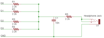
Figure 3: Monaural output mixer for headphones.
An alternative configuration allows stereo output, although the left and right channels are separated by voice, rather than arranged as the composer may have intended.
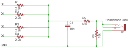
Figure 5: Mixer for driving line input on a home stereo.
For driving a stereo receiver, this output may deliver too much power. Be sure to turn the volume to the minimum setting and then adjust upward. If the primary output of the player is going to be a stereo, the circuit described in figure 5 would be preferable.
Once a mixer has been connected to the music Player, a headphone or the line input of a stereo can be connected to the polyphonic demo and tested. Beware, that the input is above standard line input voltages (line level) and a larger resistor is recommended for R5/6
A
simple resistive mixer is a low quality circuit and it is only due to the
buffers on the outputs of the Analog Shield DAC that such a simple circuit is possible
here. A more detailed discussion of mixer circuits (along with several higher
quality mixer circuits that can be built with components found in most any
parts kit) has been
written by Rod Elliot and can be found at
http://sound.westhost.com/articles/audio-mixing.htm.
How the Music Is Stored
The Polyphonic Music Player stores its output sound in the form of an array stored in program memory. Using this larger part of memory allows a much longer song to be stored but prevents the score to be modified in real time by the player itself. Changing the output song requires a new upload to the Arduino Uno. Using program memory is described in detail at http://arduino.cc/en/Reference/PROGMEM .
In order to create a new song, an array of commands and delays must be constructed. Instructions perform operations such as starting a tone generator, stopping a tone generator, ending the track, or restarting the track from the beginning. Between events, delays are inserted to pace the music.
The command to start a tone generator is of the format ‘0x9n’ where ‘n’ is a number between 0 and 3 indicating which tone generator to start. This command must be followed by an integer indicating which MIDI note to start the generator at. There are 128 MIDI notes which span five octaves, from 8Hz to 12.5kHz. A full listing of MIDI notes can be found at
http://www.tonalsoft.com/pub/news/pitch-bend.aspx.
For example, in order to start generator 1 playing midi note 60 (middle C, 262 Hz), add 0x91, 60 to the array.
The command to stop a tone generator is of the format ‘0x8n’, which simply stops the appropriate tone generator. For example, to stop tone generator number 0, add 0x80 to the array.
Between events, there must be delays. These delays come in the form of two integers. These numbers represent a 15 bit integer counting milliseconds until the next event (this means that the maximum number of milliseconds that can be delayed is 32767). For example, to add a delay of 2 seconds, 0x07, 0xd0 would be added to the array.
Finally, to stop or loop the playback, the command is 0xf0 (to stop) and 0xe0 to loop the output back to the start of the track.
A simple example output song would be:
{ 0x90, 20, 0x07, 0xD0, 0x91, 30, 0x03, 0xE8, 0x92, 40, 0x05, 0xDC, 0x80, 0x05, 0xDC, 0xF0}
This corresponds to the sequence of commands:
{START GENERATOR 0, MIDI NOTE 20, DELAY 2000ms, START GENERATOR 1, MIDI NOTE 30, DELAY 1000ms, START GENERATOR 2, MIDI NOTE 40, DELAY 1500ms, STOP GENERATOR 0, DELAY 1500ms, END TRACK}
Converting a MIDI for the Player
A utility called Miditones exists which takes a MIDI file as input and outputs an array in the format used by the player. The program is open source and available on Google code at https://code.google.com/p/miditones. Unfortunately, the version on Google code is not compiled for OSX, so included with the polyphonic player download at https://github.com/wespo/Polyphonic_music are Windows and Mac compiled binaries of Miditones along with the source code.
The primary limitation of the Polyphonic MIDI player is that it only has four voices. Although this is better than the best internal Arduino tone generator, there are many midi files with more than four voices. Be aware that complex tracks may have “missing” portions if too many voices are cut out in the conversion process.
Once a suitable midi file is ready, download the Miditones program from Google code. It is easiest to download Miditones to a default directory, such as “downloads” as it will be easier to find and use on the command line.
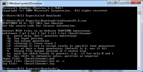
“Miditones” must be run from a command window. The command window can be found by searching for CMD on windows).
From the command window, navigate to the folder which contains miditones (if the command window opens in “C:\Users\<your username>\”, typing “cd Downloads” will work.
Try executing Miditones with no optional parameters by typing “miditonesV1.6.exe”. Miditones will display a manual page which explains various useful options.
To convert a file, execute Miditones with the filename as a parameter. It is also useful to limit the number of output voices to four with the “–t4” option. Four is the maximum number of channels that the Midi Player will output, and additional channels will waste memory but not play back sound.
For example, for a file “song.mid”, with a four voice limit, the command would be:
miditonesV1.6.exe –t4 song
Including the .mid extension to the file name will cause an error.
The output will look like the figure below.
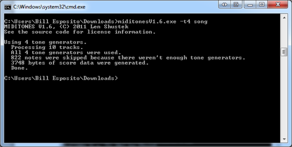
Once Miditones reports that it has produced an output, it will be stored in a file with the same name as the input midi but a .c extension (in the example, “song.c”). This file can be opened with any text editor (notepad will do), and the text is ready to copy into the polyphonic MIDI player Arduino sketch.
Adding Music to the Player
To copy the song into the Arduino sketch, replace the array named ‘score’ that starts on line 17 of the sketch, just below the comment “PASTE YOUR SONG HERE” and above the comment “Analog Shield Library”
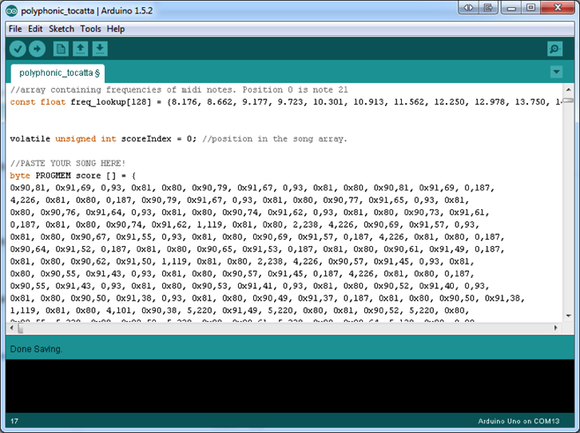
Figure 8: Insertion location for the song.
Once the new song is pasted into the sketch, it is ready to upload. Note, that a long or particularly complex music file can cause the Arduino to run out of memory and compilation to fail.
If the song is too long, array elements can be deleted, which will truncate the song, but save memory. To truncate the song, delete array elements to (but not including) an “0x80”, “0x81”, “0x82” or “0x83” and add an “0xf0” command. So long as the last element of the array is 0xf0, the song will end properly. These ‘0x##’ commands are hexadecimal instructions.
How the Code Works
The actual code of the Polyphonic music Synthesizer is based on the Analog Shield DDS routine described in Instructional materials available online at http://www.analogshield.com. The routine has been extended to support four channels of output, at the cost of some frequency precision and bandwidth.
Unlike the single channel DDS routine, the polyphonic music player can only generate sine waves; output becomes unreliable for notes above 8kHz (which manifests in the form of tones modulated on the 20kHz sample clock).
With the DDS acting as a four channel tone generator, the main loop drives the DDS by reading the score array and parsing the commands therein which are a series of instructions to set a tone generator to a certain frequency, stop a tone generator, or wait a set amount of time.
When the main loop reaches the end of the array, it will either begin again or simply stop playback, as determined by the last element of the array (either 0xf0 or 0xe0).
The
code for the polyphonic music player is attached here, and can be found at
http://www.github.com/wespo/analogshield
/* Direct Digital Synthesis with LCD Output */
/* 16 bit polyphonic DDS for music generation.*/
//12 bit long sine table
PROGMEM prog_uint16_t isinTable16[] = { <full sine wave here> };
const float freq_lookup[128] = {<frequencies go here>}; //freqs of midi notes.
volatile unsigned int scoreIndex =0; //position in the song array.
byte PROGMEM score [] = {<music goes here>}; //PASTE YOUR SONG HERE!
#include <analogShield.h> //Analog Shield Library
#include <avr/pgmspace.h> //for storing sine and song
#include <TimerOne.h> //Timer
//DDS variables
volatile unsigned int tuningWord[4] = {0};
volatile unsigned int phaseAccumulator[4] = {0}; //16 bits
volatile unsigned long sampleCount =0;
volatile unsigned long nextEvent =0;
void setup(){}
void loop()
//takes user input and the goes into DDS forever.
{
Timer1.initialize(50); //Setup the timer for DDS
Timer1.attachInterrupt(dds); //start DDS
while (1) { //stay inside this loop to reduce jitter
TIMSK0 =0x00;//Turn off timers
TIMSK2 =0x00;//to reduce jitter
//enough samples have passed time to do something
if(sampleCount > nextEvent)
{
//first a byte from the array.
//This will set your nextEvent delay
byte event = pgm_read_word(score + scoreIndex);
scoreIndex++;
if(event < 0x80)
//If the highest bit is zero.
//It is a time and we want to get a delay.
{
unsigned int delayMS =
highByte(event) +
lowByte(pgm_read_word(score + scoreIndex));
scoreIndex++;
nextEvent +=20 * delayMS; //actually 19.770
}
else//some sort of command
{
if((event&0xF0) == 0x80) //start channel
{
event = event & 0x03;
tuningWord[event] = 0;
}
elseif((event&0xF0) == 0x90) //start channel
{
event = event & 0x03;
//get midi Note
byte note = pgm_read_word(score + scoreIndex);
scoreIndex++; //increment table pointer
//convert midi note into frequency
float newFreq = freq_lookup[note];
//set appropriate channel;
tuningWord[event] = (unsigned int)(newFreq * 3.28);
}
elseif(event ==0xF0) //end of song sentinel; Stop
{
tuningWord[0] = 0;
tuningWord[1] = 0;
tuningWord[2] = 0;
tuningWord[3] = 0;
while(1);
{};
}
elseif(event ==0xE0) //end of song sentinel; Repeat
{
scoreIndex = 0;
}
}
}
}; //wait forever.
}
//DDS code
void dds() //Direct Digital Synthesis Lives Here.
{
unsigned int value[4];
unsigned int tempPhase[4];
//loop
unrolled by hand because apparently the ATMEGA compiler
//doesn't understand the word
'optimize'.
//increment the phase accumulator by the value
//stored in the tuning word.
phaseAccumulator[0] += tuningWord[0]; //16 bits
phaseAccumulator[1] += tuningWord[1]; //16 bits
phaseAccumulator[2] += tuningWord[2]; //16 bits
phaseAccumulator[3] += tuningWord[3]; //16 bits
//top 12 bits of each accumulator
tempPhase[0] = (unsigned int)(phaseAccumulator[0] >> 4);
tempPhase[1] = (unsigned int)(phaseAccumulator[1] >> 4);
tempPhase[2] = (unsigned int)(phaseAccumulator[2] >> 4);
tempPhase[3] = (unsigned int)(phaseAccumulator[3] >> 4);
//look up values
value[0] = pgm_read_word(isinTable16 + tempPhase[0]);
value[1] = pgm_read_word(isinTable16 + tempPhase[1]);
value[2] = pgm_read_word(isinTable16 + tempPhase[2]);
value[3] = pgm_read_word(isinTable16 + tempPhase[3]);
//write the result to the output.
analog.write(value[0], value[1], value[2], value[3], true);
//count samples
sampleCount++;
}
Potential Improvements
The music player is an extremely satisfying application of the Analog Shield. It would be worth additional investigation to attempt to connect the Arduino to an SD card, which would provide hours of playback. Another improvement worth investigating is “soft voices”. That is, implementing software multiplexing of two voices on each channel. This could allow for an 8 voice music player, although the cost would be a further reduction in bandwidth of the synthesized output.
Another interesting modification would be to use four amplifiers and four speakers to output each voice on its own physical channel.
Disclaimer: This code and circuit was developed by William Esposito, Ph.D. Candidate in Electrical Engineering, Stanford University, in the Kovacs/Giovangrandi Laboratory in collaboration with Texas Instruments, Incorporated. All code herein is free and open source, but is provided as-is with no warranties implied or provided. Use of this code and the associated documentation is at the user’s own risk.